Post
by glovisol » Sun Feb 17, 2019 3:36 pm
HIGH IMPEDANCE FILTER CHEBYSHEV N=9 / 0.1 dB RIPPLE / 560 to 560 OHM #10
Filter practical construction - the multi-coil technique
As previusly stated, the main problem with the filter's construction was that the size of the coils developed in the prototype (#7) were too big to fit the entire filter in the die cast utility box. As nothing is really new, a technique I had seen in German surplus equipment of WW-2 came to my mind. You wind all coils on a single dielectric tube with a significant reduction is size and much easier winding of the enamelled copper wire. This is the multi-coil technique. I used a 20 mm dia. PVC electrical conduit pipe, made a drawing of the in-line positions of the 5 coils and drilled 10 holes of 2 mm diameter. The holes hold pins that are forced in and are the coil terminals.
To construct the filter, you push the first pin in, solder the coil beginning, then you wind the first coil. At the end of the winding you push another pin in and solder the end of the first coil and so on. Figures 1 and 2 give a better idea than one thousand words. The beauty of this is that, once you know the number of turns, you wind the entire filter in less than half an hour. As we have seen already, coil Q's are in the order of 150/200, so no problem with filter performance.
With this type of assembly all wiring is done on the tube itself: each coil beginning is connected to the next beginning wth bare copper wire while every coil end joins the next coil end trough a capacitor: this becomes very clear looking at the schematic (look at #7, several posts ago, to have an idea).
Another advantage of this technique is that, by replacing the wire jumpers with capacitors you have a truly balanced filter, equisymmetrical to ground. Figure 3 shows the complete filter being tested with Noise Generator/RSP1-A - RSP SAS Spectrum Analyser. Once you see that the filter is working, e.g. you did not make mistakes with coil turns, you glue the coils in place with cyanoacrylate liquid.
More in the next post.
-
Attachments
-
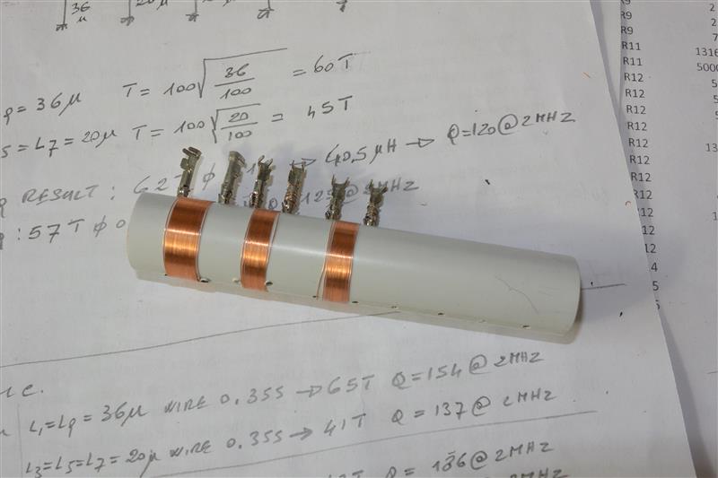
- Figure 1. Coils L1, L3 and L5 in place
- DSC_1409.JPG (62.42 KiB) Viewed 104309 times
-
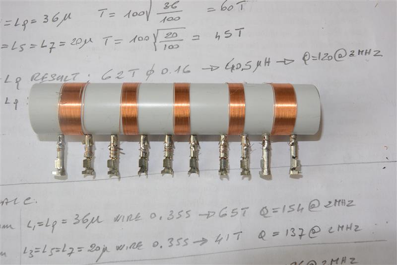
- Figure 2. All coils, L1, L3, L5, L7 & L9 in place
- DSC_1410.JPG (66.35 KiB) Viewed 104309 times
-
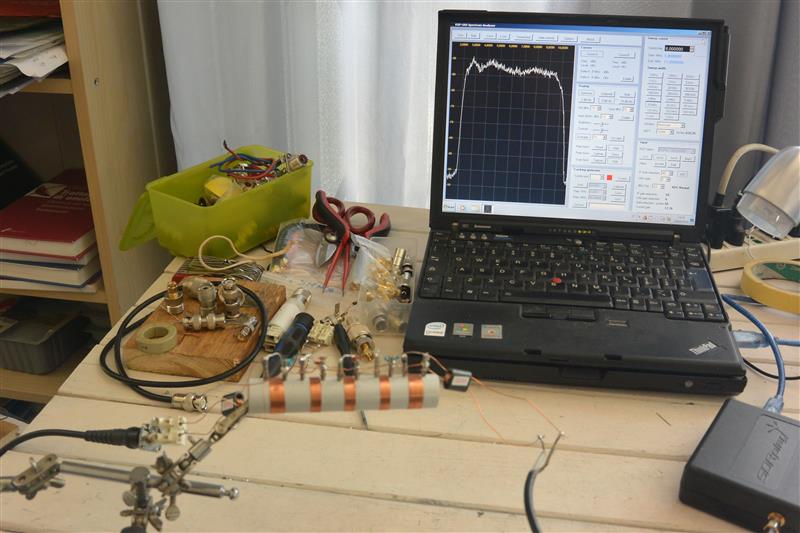
- Figure 3. Filter mounted and under test, note the binocular impedance transformer at each side for 50 Ohm matching
- DSC_1411.JPG (88.85 KiB) Viewed 104309 times
Reason: No reason