If you are a newcomer and it seems like SDRuno isn’t running or picking up any signals, CLICK HERE to check our “quick start†guide which covers the four things that are the most likely causes of initial problems.
This list of common questions (and answers) about SDRuno can also be found here: Common SDRuno questions
This list of common questions (and answers) about SDRuno can also be found here: Common SDRuno questions
SDRuno evolved from software called Studio 1 which SDRplay acquired in 2016. Studio 1 supported many SDR receivers using the EXTIO interface.
Since then we have adapted SDRuno to make optimal use of the RSP family of SDRs. Many of the recent features (such as scanning and band framing)
rely on the RSP architecture to work.
This is why the EXTIO version does not include some of the newer functions. However the EXTIO version will still offers many of the basic features found in the current SDRuno release, if you want to use it with other SDRs which support an EXTIO interface. Be sure that you are launch the right version depending on whether you have an RSP or not. (Please note that if you have an RSP and accidentally launch the EXTIO version, only the “main†control panel will appear and not all the other defaults panels).
This is why the EXTIO version does not include some of the newer functions. However the EXTIO version will still offers many of the basic features found in the current SDRuno release, if you want to use it with other SDRs which support an EXTIO interface. Be sure that you are launch the right version depending on whether you have an RSP or not. (Please note that if you have an RSP and accidentally launch the EXTIO version, only the “main†control panel will appear and not all the other defaults panels).
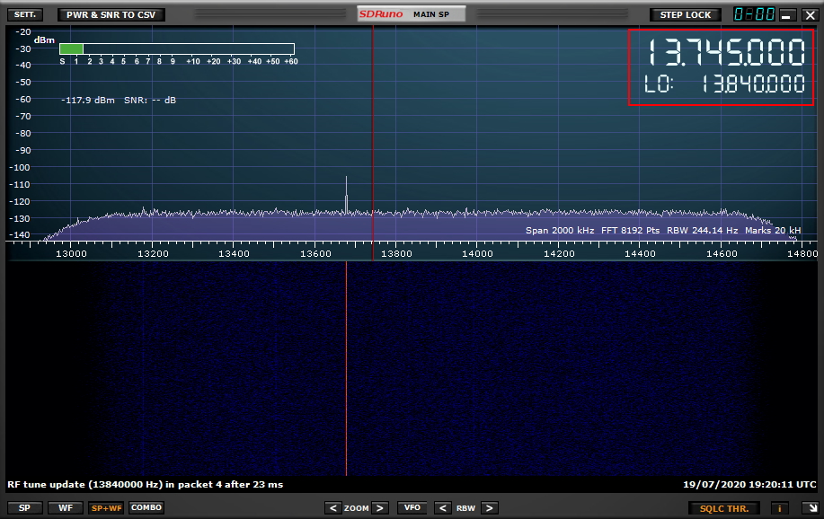
The LO is the Local Oscillator frequency of the RSP hardware, and this is the synthesizer frequency. It will always be the frequency of the centre of your main spectrum display (SP1) when fully zoomed out. The VFO is Variable Frequency Oscillator and this is used to select individual signals within the viewable spectrum. Here there is always a DC spike and the IF (intermediate frequency) mode determines where the spike appears. In ZIF (Zero IF) mode, the DC spike is at the LO frequency (0 Hz offset). Please see the FAQ video on the right.
Software is used to remove the spike which can also remove any signal at the LO frequency. This is why you need to apply an offset of a few kHz between the LO and VFO frequencies when operating in Zero IF mode. SDRuno v1.4 includes the ability to automatically generate such an offset for you. No such separation is required in LIF mode.
It is possible to run SDRuno using a Windows Virtual Machine (e.g. Parallels, Fusion or Bootcamp) on a Mac computer. It is also possible to use WINE on a Linux computer. These work quite well but our goal is to migrate to multiplatform support for SDRuno in Version 2.0.
It is on our SDRuno roadmap Although we are unable to commit a timeframe for this, updates will be published in our blog whenever possible.
It is on our SDRuno roadmap Although we are unable to commit a timeframe for this, updates will be published in our blog whenever possible.

Even if you are running your RSP off grid (no internet connected) you can access the full SDRuno manual from within the SDRuno main panel as shown below:

Alternatively you can view or download the latest version of the manual online: Downloads page
Alternatively you can view or download the latest version of the manual online: Downloads page
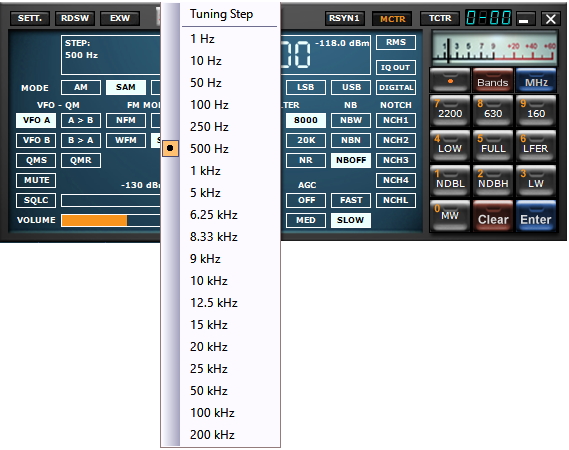
The granularity of the tuning steps is preset, but by right clicking within the RX Control frequency window, a drop down choice of “step size†will appear and you can select something more optimum for your use. This setting will be remembered until you change it again or reset all settings to default.
If you are scanning a range of frequencies (rather than using your own memory bank), it’s important to make sure that the start of the range and the step-size matches candidate signals that you are seeking. The second most important thing is to select a practical threshold for the signal strength. If set too low, then every piece of noise will be interpreted as a signal of interest. Too high and nothing will be identified.
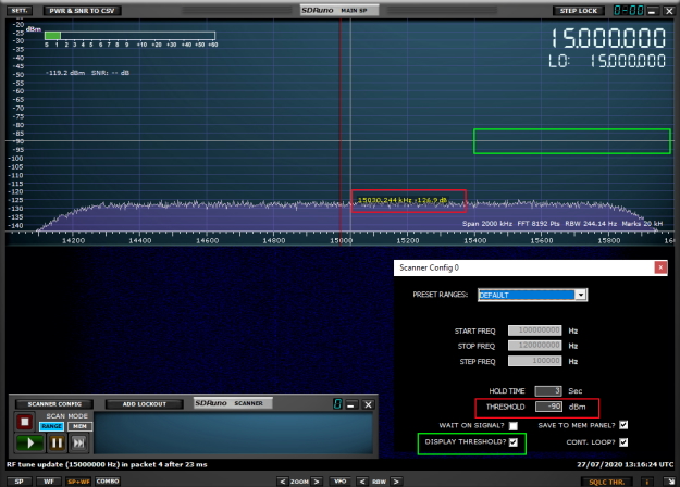
The best way to determine a good value for the threshold is to place your VFO on a quiet section of spectrum. Ensure that your filter bandwidth and demodulation choice is set to the types of signal you seek, then make a note of the noise floor on the power meter. Do not estimate the noise floor by looking at the Y-axis of the spectrum display. This will be misleading. You need to use the power meter as this integrates the noise power across the full chosen channel bandwidth. Having done this, now set your scanner threshold to be say 6 – 10 dB greater than this. Then start the scanner. See the video in the link to the right, 2 minutes, 50 seconds in.
The best way to determine a good value for the threshold is to place your VFO on a quiet section of spectrum. Ensure that your filter bandwidth and demodulation choice is set to the types of signal you seek, then make a note of the noise floor on the power meter. Do not estimate the noise floor by looking at the Y-axis of the spectrum display. This will be misleading. You need to use the power meter as this integrates the noise power across the full chosen channel bandwidth. Having done this, now set your scanner threshold to be say 6 – 10 dB greater than this. Then start the scanner. See the video in the link to the right, 2 minutes, 50 seconds in.
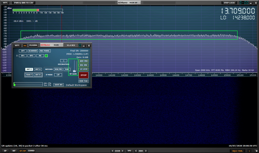
What you are seeing here is the effect of the IF filter in the tuner. For example, this starts to roll off for signals that go beyond +/- 768 kHz of the centre frequency as in Low IF mode (LIF), where the IF bandwidth is limited to 1.536 MHz.
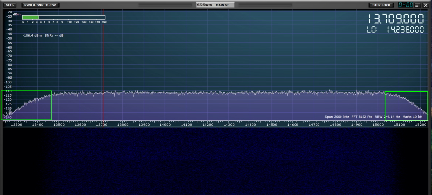
You can widen the IF bandwidth by selecting ZIF (Zero IF) as the IF mode. You can then select a higher sample rate such as say 5 MHz or higher. This will give you more of the spectrum with a flatter noise floor (assuming the floor is naturally flat over that range)
You can widen the IF bandwidth by selecting ZIF (Zero IF) as the IF mode. You can then select a higher sample rate such as say 5 MHz or higher. This will give you more of the spectrum with a flatter noise floor (assuming the floor is naturally flat over that range)
The software is designed to auto-populate with a layout that is defined by the screen resolution.
There are some screen resolutions that we have not encountered before and so they are not supported for auto-population.
Some of the panels in SDRuno are fixed number of pixels in size and so cannot be stretched.
(This is a legacy from when the software was known as Studio 1 and pre-dates our involvement with its development. We do plan to change this when we re-design the GUI in release 2.0)
Meanwhile, if this applies to you and laptop screen is small, then we recommend that you reduce your screen resolution. This will increase the size of the non-adjustable panels and then you can pick a supported screen resolution so that auto-population feature will now work. The supported screen resolutions are listed in section 3.9 of the user manual. If you are unable to select one of these resolutions, then you can manually open the panels and design a workspace that suits you best and then save it be pressing the SAVE WS (Save Workspace) button on the Main Panel. That way the workspace will always open this way when you start the software. Autopopulate is demonstrated 45 seconds in, in the SDRuno basics video link on the right
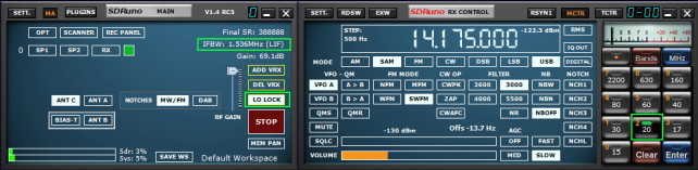
If you choose one of the preset bands within SDRuno it will put the radio into Low IF (LIF) mode and lock the LO as part of the band framing process. The band button will be illuminated green. This will automatically select the appropriate sample rates to ensure the desired band fills the spectrum window in its entirety, and you will only be able to tune frequencies within that band (to prevent you wasting time by inadvertently scrolling outside the band). If you subsequently wish to select frequencies outside that band (for example by tuning the master VFO frequency in the RX Control panel) just “unframe†the band by selecting the band button so that the green light goes out, or turn off the LO LOCK button.
The same is true of you are using Omnirig and want to tune SDRuno from your transceiver. In that situation you will need to turn off LO LOCK in SDRuno so that the rig can command a frequency outside the currently framed band. You may then freely change bands and VFO frequencies from the rig, however you will not be able to use the band framing feature unless you select the band od interest from SDRuno. Just make sure that if you want to change bands from the rig, you first ensure the LO LOCK is turned off in SDRuno.
This is because SDRuno always displays the “equivalent noise†at the antenna input of the RSP. What do we mean by “equivalent†noise? A perfect receiver would not add any noise to the received signal. A practical receiver will always add noise due to the imperfections of the mixer and amplifier circuits. As you reduce the RF amplifier gain the noise degradation in the receiver will get worse. SDRuno calculates this and the S meter and spectrum display accordingly. What you observe is that the “noise floor†of the receiver gets worse (increases) as you reduce the gain. The received signal however does not change and will display approximately the same level.
Try this experiment. Tune in a local MW station in AM mode with 6000 Hz. bandwidth. Observe the S meter, the dBm level and the signal-to-noise-ratio (SNR) at maximum RF gain (without overload flashing). Now slowly reduce the RF gain and you will see the following. The signal level on the S meter and dBm level will remain the same (within a few dB or so) but the SNR will slowly get worse. The noise floor of the entire band on the spectrum display will get higher. That is because the internal noise of the RSP is getting worse as you lower the gain and this results in a poorer SNR. It also means weak stations are starting to get buried in receiver noise.